In the biotechnology and pharmaceutical manufacturing sectors, there is no single event more universally dreaded by process engineers than a batch contamination. Whether you are cultivating recombinant proteins, performing precise enzymatic hydrolysis, or scaling up a pilot vaccine batch, the biological environment inside a reactor is a double-edged sword. The very conditions that allow your target organism or enzyme to thrive—high humidity, exact isothermal heat, and abundant carbon sources—make the reactor an ultra-attractive breeding ground for unwanted wild yeasts, bacteria, and bacteriophages.
On engineering communities like Reddit and Quora, a recurring cry for help from lab technicians and plant managers alike is: “Every single batch is contaminated, what is going wrong?” Often, the team has meticulously followed chemical sanitation SOPs, yet the infection persists.
The harsh reality of industrial bioprocessing is that standard chemical sanitization (which merely reduces microbial population) is insufficient for high-purity cultivation. To achieve true sterile integrity, robust bioprocess contamination prevention must be engineered directly into the physical structure, fluid dynamics, and thermodynamic boundaries of the ステンレス鋼反応炉.
In many bioprocessing facilities, contamination is a silent and deceptive enemy. During the early stages of a fermentation run, everything may appear normal. However, as noted in troubleshooting threads, subtle anomalies usually surface around the 24-to-48-hour mark:
By the time these physical symptoms manifest, the batch is already lost. Why? Because the contaminant was often already hiding inside the reactor’s physical infrastructure, shielded from standard sanitization protocols. Implementing comprehensive bioprocess contamination prevention requires understanding how these microscopic invaders bypass standard cleaning procedures.
Before exploring macro-structural fixes, we must address the microscopic interfaces of the vessel. On forums, many engineers discuss how “micro-scratches in steel” lead to repeated infections. Under a scanning electron microscope (SEM), even highly polished industrial-grade steel reveals a landscape of microscopic “canyons” and valleys.
Bacteria (typically 0.5 micrometers to 2.0 micrometers in size) settle into these microscopic valleys. Over time, they secrete a slimy, protective matrix of extracellular polymeric substances (EPS), creating a biofilm.
Once a biofilm anchors to the steel, it becomes highly resilient. The outer layers sacrifice themselves to shield the bacteria underneath from sanitizing chemicals like sodium hydroxide (NaOH) or high-temperature steam. During the next batch cycle, the biofilm releases active bacteria directly into the fresh media.
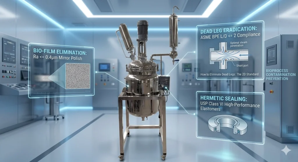
To achieve successful bioprocess contamination prevention, international standards (such as ASME BPE) require a mirror-polished interior surface with a roughness rating of Ra <= 0.4 micrometers (typically accomplished via mechanical polishing followed by electropolishing). At this level, the microscopic “valleys” are smaller than the bacteria themselves, leaving no physical anchor points for biofilm formation and allowing Clean-in-Place (CIP) fluids to achieve 100% fluid shear-cleaning efficiency across the boundary layer.
Often overlooked in biofilm discussions is the degradation of polymer gaskets (EPDM, PTFE, or Silicone) at connection joints. Under repeated SIP (Sterilization-in-Place) thermal cycles, sub-standard elastomers develop micro-fissures. These microscopic cracks act exactly like unpolished metal crevices, shielding bacterial spores from steam. High-tier reactors must exclusively utilize USP Class VI and FDA-compliant elastomers that resist thermal compression set, maintaining a flush, hermetic seal over hundreds of autoclave runs.
In sanitary fluid systems, a “Dead Leg” is an area of stagnation—typically a nozzle, T-junction, or instrument branch—where fluid or air can become trapped and isolated from the main flow of sterilization steam or cleaning solvents.
理解how to eliminate dead legs is the single most critical engineering step in comprehensive bioprocess contamination prevention.
STAGNANT ZONE (Dead Leg)
┌──────────────────────┐
│ Contaminated Media │ <── No CIP flow can reach here
│ & Stagnant Water │
└──────────┬───────────┘
│
│ ◄── L (Length of nozzle)
│
MAIN FLOW ─────┴───────────► D (Diameter of nozzle)
During a Sterilization-in-Place (SIP) cycle, saturated steam is introduced to raise the system temperature to 121 degrees Celsius or 131 degrees Celsius (targeting a minimum F0 sterilization value to guarantee the destruction of highly heat-resistant spores like Geobacillus stearothermophilus).
However, if a nozzle is too deep, the steam cannot displace the heavier, cooler air trapped at the closed end of the branch. Because air is an excellent thermal insulator, this area remains a “cold pocket” that fails to reach sterilization temperature. The resident bacteria survive the thermal cycle, waiting to compromise the fresh culture media as soon as agitation begins. This illustrates why knowing how to eliminate dead legs is paramount to maintaining a sterile environment.
Furthermore, during Clean-in-Place (CIP) cycles, the turbulent flow of cleaning chemicals cannot reach the back of a deep branch. Under fluid dynamics principles, when the Reynolds number (Re) of the fluid flowing through the main line is high, it creates a recirculating vortex at the entrance of the dead leg, but the shear stress decay is exponential:
Wall Shear Stress (Tau) is proportional to e^(-alpha * (L/D))
Where L/D is the length-to-diameter ratio. If the dead leg is too deep, the cleaning fluid cannot exert enough mechanical force to dislodge biofilms. To resolve this, engineers must understand how to eliminate dead legs through geometry.
To implement effective bioprocess contamination prevention, engineers must design piping and port interfaces that minimize stagnant volume.
The primary rule on how to eliminate dead legs is strict adherence to the ASME BPE guidelines. The length (L) of any stagnant pipe, nozzle, or instrument branch—measured from the inner wall of the main flow to the seal point or gasket—should ideally not exceed two times its inner diameter (D): L/D <= 2
Historically, an L/D ratio of 3:1 was accepted, but high-purity biological processes now mandate the stricter 2D standard to guarantee absolute thermal displacement and cleaning fluid penetration. Understanding how to eliminate dead legs using this 2D rule is the foundation of modern sanitary piping design.
Achieving complete sterile integrity requires replacing standard industrial fittings with specialized, sterile-grade components designed to prevent contamination at the physical boundaries of the vessel. This hardware overhaul is critical for long-term bioprocess contamination prevention.
Below is the structural schematic of a modern, highly integrated pilot-scale reactor designed to address these exact contamination vectors.
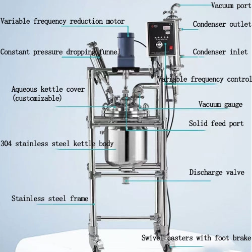
Figure 1: Anatomy of a Sanitary Pilot-Scale Stainless Steel Reactor with Integrated VFD Controls and Distillation Accessories.
As shown at the top of Figure 1, a professional-grade unit features a top-mounted Variable Frequency Geared Motor coupled with a Variable Frequency Control panel. This VFD integration is vital for bioprocess contamination prevention: running the agitator at excessively high speeds with viscous media can generate localized friction heat at the seal interface. This localized hot zone can cause 熱変性 of proteins or caramelize sugars in the media, creating a burnt nutrient layer that serves as a breeding ground for bacteria.
Directly beneath this drive assembly lies the most critical dynamic barrier: the Double Mechanical Seal.
Unlike standard lip seals, a double mechanical seal utilizes a pressurized sterile barrier fluid (typically USP-grade water or clean steam condensate) circulating between two seal faces. The barrier pressure is maintained at least 0.05 MPa to 0.1 MPa higher than the internal reactor pressure. If any micro-wear occurs on the rotating faces, the sterile barrier fluid leaks slowly inward, ensuring that external atmospheric bacteria can never migrate outward into the sterile batch.
During active fermentation or vacuum-assisted concentration, gas must escape the vessel. This exhaust process introduces a major risk: aerosol-borne pathogens back-flowing into the reactor from the environment when the vacuum pressure shifts.
The introduction of raw materials mid-process (such as nutrients or pH adjusters) is another high-risk step.
そのCustomizable Vessel Head (noted as the Aqueous kettle cover in Figure 1) is engineered with heavy-duty sanitary Tri-Clamp ports. It accommodates an Equal-Pressure Feeding Funnel (Constant pressure dropping funnel). This closed-system configuration allows operators to introduce fluids under complete isolation or vacuum, eliminating the risk of airborne pathogens entering the headspace during mid-cycle additions.
Standard bottom outlet valves (such as basic ball valves) are notorious for creating a large dead leg between the valve ball and the floor of the vessel. This neck of trapped, stagnant fluid escapes both mixing and sterilization.
To eliminate this ultimate dead leg, the unit shown in Figure 1 utilizes a specialized 排出弁 at the absolute lowest point of the domed bottom. In a sanitary configuration, this is a Radial Diaphragm Tank Bottom Valve. The elastomer diaphragm seals perfectly flush with the inner radius of the vessel bottom. Consequently, the L/D ratio at the discharge port is reduced to zero (L/D = 0). Knowing how to eliminate dead legs at the drain port ensures that every drop of product is fully sterilized during the cycle, and 100% gravity-drained during harvesting.
| Critical Point | Sanitary Bio-Pharma Solution (Optimized) | Contamination Defense Mechanism |
| Vessel Body | SUS316L / Ra <= 0.4 micrometers Mirror Polish | Eliminates microscopic crevices; prevents biofilm formation and cell adhesion. |
| Drive Assembly | VFD Geared Motor + Double Mechanical Seal | Precise speed control prevents friction-heat denaturation; high-pressure barrier prevents microbial ingress along the shaft. |
| Dead Leg Control | ASME BPE compliant L/D <= 2 Design | Eliminates stagnant cold air pockets; ensures 100% steam penetration during SIP. |
| Gaskets & Seals | USP Class VI High-Performance Elastomers | Prevents micro-fissure formation under repeated steam-thermal expansion cycles. |
| Feeding Port | Equal-Pressure Dropping Funnel | Maintains complete hermetic sealing during mid-process chemical or nutrient additions. |
| Outlet Valve | Radial Diaphragm Discharge Valve (L/D = 0) | Eliminates stagnant fluid “pockets” at the discharge port, enabling complete sterility. |
For laboratories, small-scale workshops, and pilot plants that do not have the luxury of fully automated, multi-million dollar cleanroom facilities, maintaining sterile integrity and enforcing bioprocess contamination prevention comes down to smart equipment design and disciplined protocols:
By addressing the war on contamination through material science and mechanical engineering, bioprocessing facilities can transform sterile processing from a game of chance into a predictable, highly repeatable science.
Q: What is the difference between “Sanitization” and “Sterilization” in bioprocessing?
A: Sanitization: Reduces active microorganisms to a safe level (typically a 99.9% or 3-log reduction) using chemicals. It does not kill highly resilient bacterial endospores. Sterilization: The absolute elimination of all microbial life, including spores (achieving a 10^-6 Sterility Assurance Level / 6-log reduction) via high-temperature steam (SIP) or validated autoclaving. For robust bioprocess contamination prevention, sterilization is mandatory.
Q: Why are standard ball valves and threaded connections banned in sanitary reactors?
A: Threaded Fittings: Leave microscopic gaps between metal threads that trap liquids. Cleaning fluids cannot flow into these gaps, directly violating dead-leg rules. Standard Ball Valves: Have a hollow internal cavity around the rotating ball. When closed, product becomes trapped inside, shielded from Clean-in-Place (CIP) flow, leading to rot and cross-contamination. The Standard: Only flush-mounted Radial Diaphragm ValvesまたはSanitary Tri-Clamp fittings with USP Class VI gaskets are permitted.
Q: How do I calculate and identify a dead leg on my existing reactor setup?
A: Measure (D): The internal diameter of the nozzle or pipe opening. Measure (L): The length from the main pipe’s inner wall to the absolute seal point (the valve seat or gasket face). Calculate: Divide L by D (L/D ratio). If L/D is greater than 2 (L/D > 2), you have a non-compliant dead leg. During SIP, steam cannot displace the cold air trapped inside, creating a non-sterile cold spot. To solve this, you must shorten the nozzle neck or transition to a flush-mounted tee-junction.